R/D Converters (Smartcoder)
Smartcoder is a R/D (Resolver to Digital) conversion IC, which converts resolver signals into digital absolute position angle signals.
It is usable in a wide range of applications, including vehicle/robot/machine tool related applications, in combination with brushless resolvers such as our Smartsyn and Singlsyn.
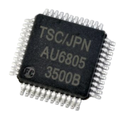
The photo is an image.
User's Manual
Features
- ・Adopts R/D conversion based on a proven digital tracking system
- ・Low cost, small size and light weight
- ・Satisfying fail check functions
(1) Abnormality detection
Capable of detecting abnormal resolver signals, breaking of resolver signals, abnormal R/D conversion and abnormally high temperature of a IC
(2) Built in self test
Conducts a self test on R/D conversion and abnormality detection - ・Realization of system/cost reduction based on all-in-one concepts
(1) Integrated with an excttation amplifier (Output current: 10mA rms/20 mA rms)
(2) Integrated with an operation clock - ・Enhancement of functions corresponding to various applications
(1) Requires no phase adjustment to excitation signals (Allowable range: Within土45 ゜)
(2) Variable setting of controlling bandwidth (fBW) (Selectable from 7 types of fixed values or automatic adjustment)
(3) Capable of digital conversion of linear hall IC signals and R/D parallel connections to resolvers
(4) Output redundancy (Triple redundancy-Parallel/Pulse/Serial output)
Specifications
| Model | AU6805 |
|---|---|
| Resolution | 4,096(=212) |
| Tracking rate | 240,000 min-1( When fBW is fixed.) |
| Conversion accuracy | ±4 LSB |
| Max. angular acceleration | 3,000,000 rad/s2(When fBW is automatic adjustment.) |
| Settling time | 1.5ms(When input step is 180 ゜,and fBW is automatic adjustment.) |
| Output response | ±0.2 °/10,000 min-1 |
| Output form | 12 bit binary code Positive logic parallel+ A,B,Z + Serial 1/F |
| Power requirement | +5 V±10 % (45 mA: When the excitation amplifier is set at 10 mArms.) |
| Excitation power supply | Integrated with a constant current control method excitation amplifier (10 mArms / 20 mA rms) |
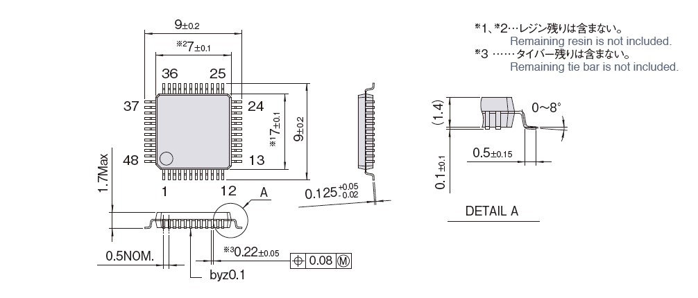
| Outline | 48 pin LQFP(7×7)、Pin to pin: 0.5 mm |
| Operating temperature | -40 to +125 ℃ |
Outline
Dimension:mm
Functional Block Diagram
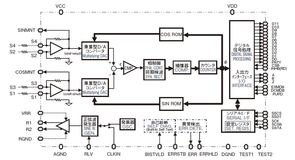
Pin Description
| No. | Symbol | Class | Remarks | No. | Symbol | Class | Remarks | No. | Symbol | Class | Remarks | ||
|---|---|---|---|---|---|---|---|---|---|---|---|---|---|
| 1 | EXMDB | D/I | Ext. excit. sig. source mode | 17 | CLKIN | D/I | Clock input | 33 | D3 | D/O (BUS) |
Phase U/φ9 | ||
| 2 | DCMDB | D/I | DC resolver mode | 18 | SSDT | D/I | Serial setting data | 34 | D2 | D/O(I) | Phase Z/φ10 | ||
| 3 | RLV | D/I | Excitation current select | 19 | SSCS | D/I | Serial setting CS | 35 | D1 | D/O (BUS) |
Phase B/φ11 | ||
| 4 | VCC | - | Analog power supply | 20 | DATA | D/O (BUS) |
Serial data | 36 | D0 | D/O (BUS) |
Phase A/φ12 | ||
| 5 | SINMNTB | A/O | SIN monitor | 21 | SCSB | D/I | Serial CSB | 37 | VDD | ― | Digital PS | ||
| 6 | COSMNT | A/O | COS monitor | 22 | PRTY | D/O (BUS) |
Parity | 38 | INHB(RD) | D/I | Inhibit | ||
| 7 | A GND | - | Analog GND | 23 | SCK | D/I | Serial clock | 39 | ERRHLD | D/O(I) | Error (Hold) | ||
| 8 | S3 | A/I | S3 input | 24 | DGND | - | Digital GND | 40 | ERRSTB | D/I | Error reset | ||
| 9 | S1 | A/I | S1 input | 25 | D11 | D/O (BUS) |
ERRCD3/φ1 | 41 | ERR | D/O(I) | Error outputr | ||
| 10 | S2 | A/I | S2 input | 26 | D10 | D/O (BUS) |
ERRCD2/φ2 | 42 | A | D/O | Phase A pulse output | ||
| 11 | S4 | A/I | S4 input | 27 | D9 | D/O (BUS) |
ERRCD1/φ3 | 43 | B | D/O | Phase B pulse output | ||
| 12 | R GND | - | GND:Excitation amp. GND | 28 | D8 | D/O (BUS) |
ERRHLD/φ4 | 44 | Z | D/O(I) | Phase Z pulse output | ||
| 13 | R2 | A/O(I) | Excitation output R2 | 29 | D7 | D/O (BUS) |
ERR/φ5 | 45 | CSB | D/I | Chip select | ||
| 14 | VRR | - | BUS output select 1 | 30 | D6 | D/O (BUS) |
-/φ6 | 46 | PUPD | D/I | Paral. abs. upd. sw. | ||
| 15 | R1 | A/O(I) | Excitation output R1 | 31 | D5 | D/O (BUS) |
Phase W/φ7 | 47 | TEST1 | D/I | (Test mode setting) | ||
| 16 | BISTVLD | D/I | BIST execution control | 32 | D4 | D/O (BUS) |
Phase V/φ8 | 48 | TEST2 | D/I | (Test mode setting) |
Note :
1.“No.” corresponds to the pin number of terminal.
2.“Class” means the following:
*A/I : Analog input
*A/O : Analog output
*A/O(I) : Analog output (I/O is switched by control terminal input.)
*D/I : Digital input
*D/O : Digital output
*D/O(I) : Digital output (Input is added internally.)
*D/O(BUS) : Digital output (3-state output)
3. No.47 TEST1 signal and No. 48 TEST2 signal are signals that do not directly participate in operations, and normally, TEST1 is bypassed with the digital power supply (VDD) and TEST2 with digital GND (DGND). When they are not connected to anything, they are internally pulled up or pulled down respectively.
Smartcoder AUA6805 Evaluation Board | AUA212
・RoHS
・Power supply : DC+5 V ±10 %
Note :
Operation is not guaranteed as this product is for the evaluation test.For details, please contact the Sensortronics Laboratory.
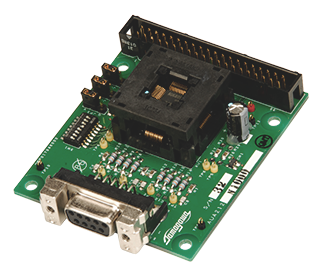
Outline

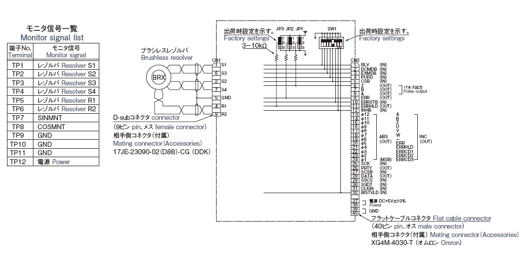
External Connection
