04Step Motors/Drivers
Home > Products - Step Motors/Drivers
Simple positioning control by high torque and sensorless motors
Abundant lineup correcsponding to various application
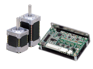
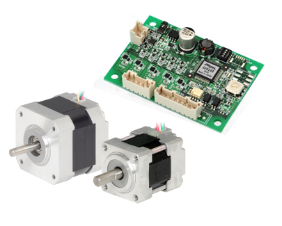
Step Motors/Drivers
Step Motors/Drivers
The step motor is a motor that can perform open loop control without the need for a feedback mechanism. It features small size, light weight, high torque, and low price. This type of motor can be controlled more simply than a servo motor.